Front End System of Ooty Radio Telescope
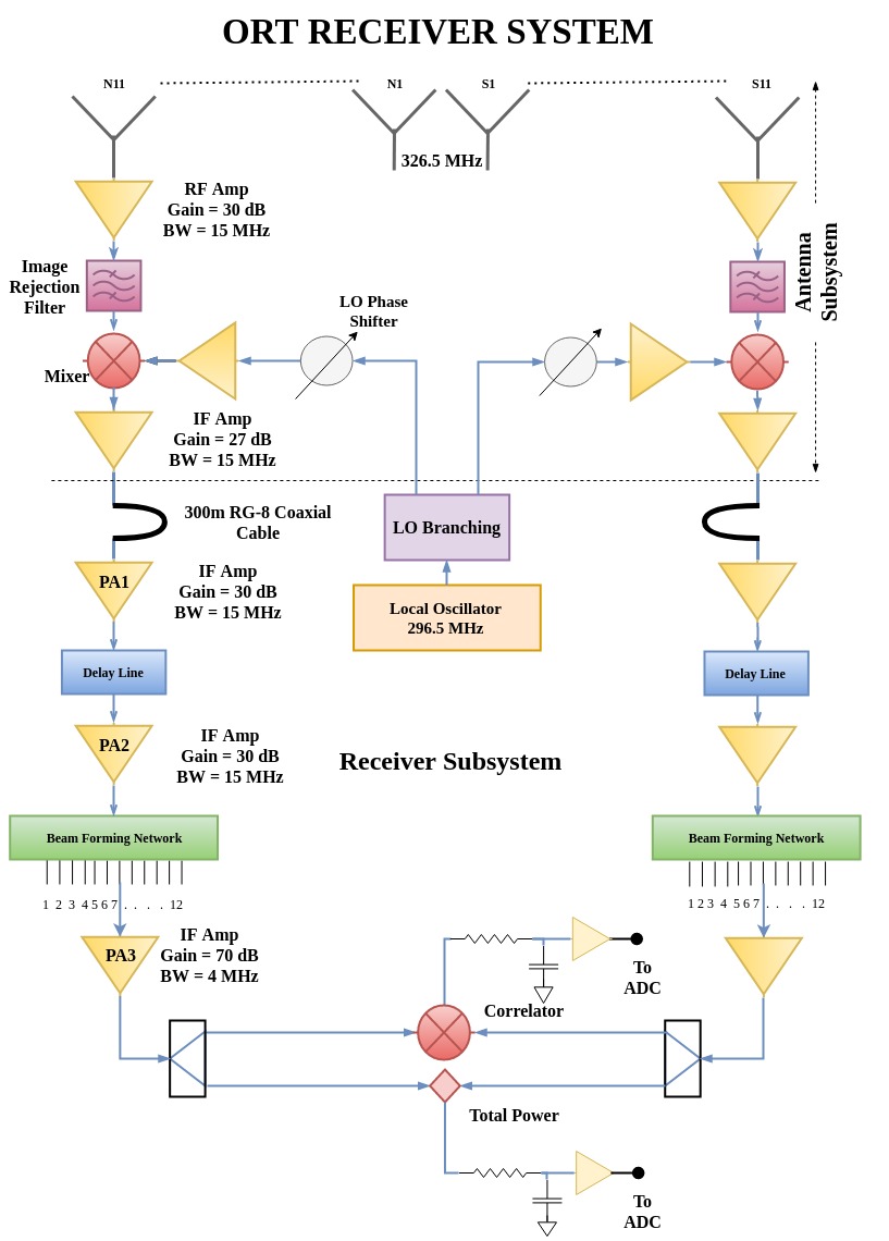
Schematic diagram shows the signal flow of ORT
The front-end reciever system of the ORT was upgraded with a low noise amplifier (Tamp = 50 K) and a strip line diode-switch controlled phase shifter following each of the 1056 dipoles. This upgradation improved the sensitivity of the system by a factor of two. Additionally the declination-setting and monitoring system was computerized leading to enhanced stability. A new local oscillator phase shifter with increased accuracy has improved the response of ORT over the entire 15 MHz bandwidth and also increased the declination range visible to the ORT. The present system supports electronic steering to declinations between -60 and +60 degrees.
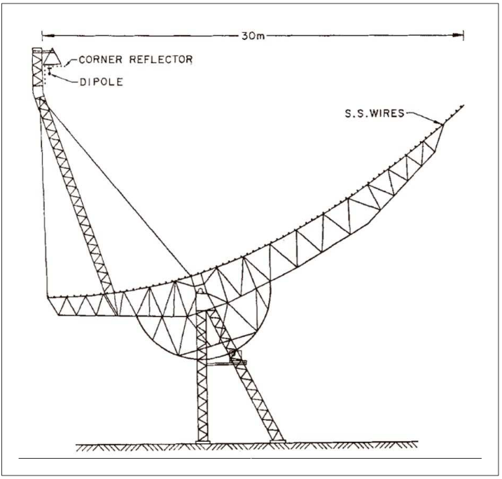
A cross section sketch of one frame of ORT showing details
The Receiver:
An array of 1056 half-wave dipoles in front of a 90 degrees corner reflector forms the primary feed of the telescope. The signals recieved by groups of 48 dipoles are added in-phase to form 22 group outputs, each known as a module . The northern modules are designated as N1 to N11 and southern modules as S1 to S11. The signal from each module are down-converted to an IF of ~30 MHz with a bandwidth of 15 MHz at the front-end. The LO signal for the downconversion is transmitted to all the modules over equal-length cables from a common source in the receiver room.
The beam width due to each module is 2.3 degs in EW and 2.2 degs secant of declination (sec(dec)) in the NS. The outputs from the 22 modules of the ORT are brought to the receiver room for further processing. The 11 north signals and 11 south signals are separately combined in a beam-forming network with proper delay compensations. This compensation for different geometric path lengths between the different modules generates 12 beams for each half of the ORT. The telescope can be operated in either total power or correlation mode.
In the total power mode, the 12 beams each from north and south are added to generate a beam with width of 2.3 degs in EW and 5.5' sec(dec) in the NS. In the correlation mode, the beams from the north and the south are multiplied to generate the correlation beams with a width of 2.3 degs in the EW and 3.3' sec(dec) in the NS. The adjacent beams are separated by 3'sec(dec) . The twelve beams are called Beam 1 (southern most beam) to Beam 12.
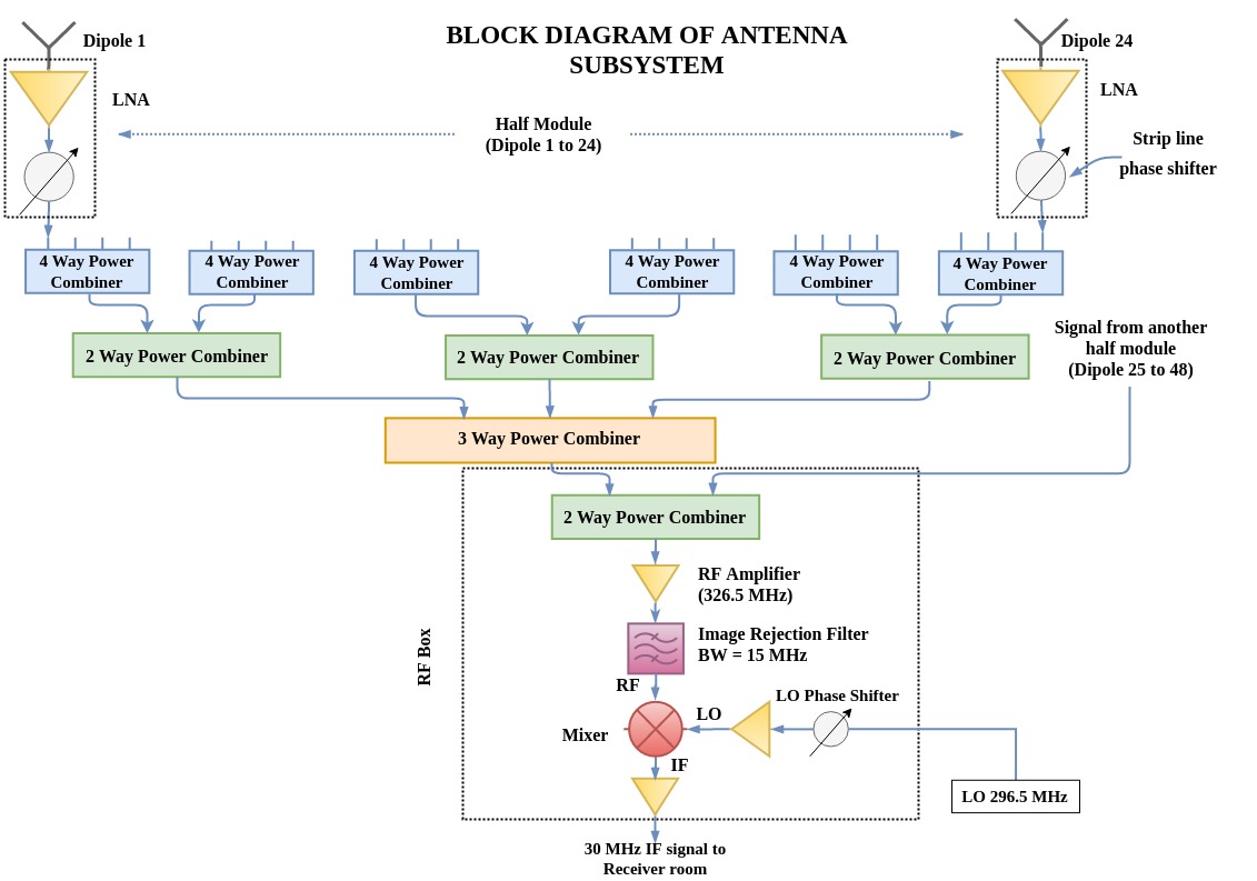
Schematic diagram of Antenna Subsystem