Ooty Wide Field Array(OWFA)
We describe here an ongoing upgrade to the legacy Ooty Radio Telescope (ORT). The ORT is a cylindrical parabolic cylinder 530mx30m in size operating at a frequency of 326.5 (or z ~ 3.35 for the HI 21cm line). The telescope has been constructed on a north-south hill slope whose gradient is equal to the latitude of the hill, making it effectively equitorially mounted. The feed consists of an array of 1056 dipoles. The key feature of this upgrade is the digitisation and cross-correlation of the signals of every set of 4-dipoles. This converts the ORT into a 264 element interferometer with a field of view of 2 degrees x 27cos(delta) degrees . This upgraded instrument is called the Ooty Wide Field Array (OWFA).
Salient features of the upgrade, as well as its main science drivers. There are three main science drivers viz.
- Observations of the large scale distribution of HI in the post-reionisation era.
- Studies of the propagation of plasma irregularities through the inner heliosphere.
- Blind surveys for transient sources.
Introduction
The legacy Ooty Radio Telescope (ORT) is being reconfigured as a 264-element synthesis telescope, called the Ooty Wide Field Array (OWFA). Its antenna elements are the contiguous 1.92 m sections of the parabolic cylinder. It will operate in a 38-MHz frequency band centred at 326.5 MHz and will be equipped with a digital receiver including a 264-element spectral correlator with a spectral resolution of 48 kHz. OWFA is designed to retain the benefits of equatorial mount, continuous 9-hour tracking ability and large collecting area of the legacy telescope and use of modern digital techniques to enhance the instantaneous field-of-view by more than an order of magnitude. OWFA has unique advantages for contemporary investigations related to large scale structure, transient events and space weather watch.
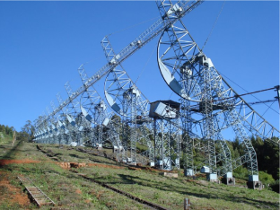
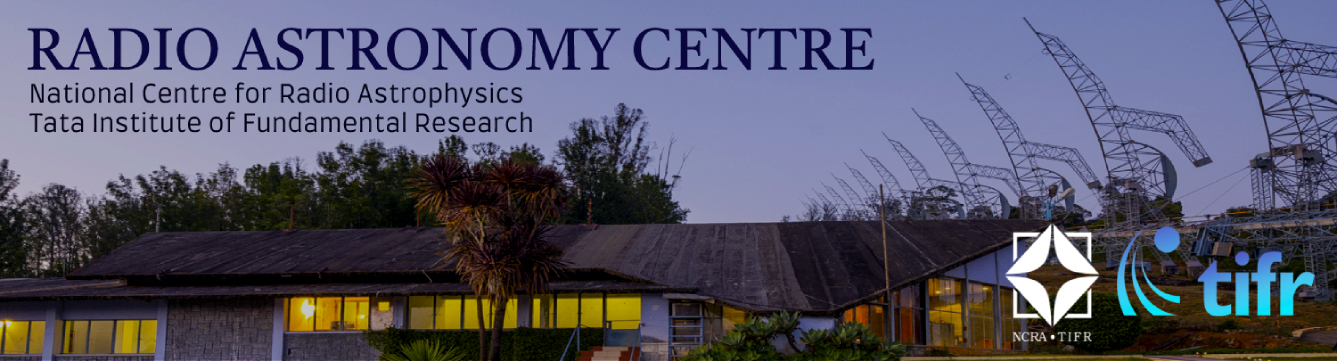
Figure 1: The Ooty Radio Telescope is an offset cylindrical paraboloid, 530mx30m in size. It is equitorially mounted. The Ooty Wide Field Array (OWFA) is an upgrade to the ORT, which digitizes the signals from every 4 dipoles along the feed line. These signals are then cross-correlated, leading to a very wide field of view interferometer. See the text for more details.
Description
This article describes the Ooty Wide Field Array (OWFA) which is an ongoing upgrade of the Ooty Radio Telescope (ORT). The ORT (Swarup et al., 1971) is an offset parabolic cylinder 530mx30m in size commissioned in 1970. The telescope is mechanically steerable about the long axis of the cylinder. This axis is mounted along a hill whose slope is the same as its latitude, effectively making the telescope equitorially mounted. The sky can hence be tracked by rotation about the cylinder axis. The telescope has a line focus, along which is placed an array of 1056 dipoles. Each dipole is followed by a Low Noise Amplifier (LNA) as well as a 4-bit phase shifter(Selvanayagam et al., 1993). The dipoles are grouped into 22 “modules” with each module consisting of 48 dipoles.
In the legacy system the phased output of all modules are combined with appropriate phase and delay correction to produce up to 12 equispaced beams covering 36
′
in the north-south direction. The delays and phases can also be adjusted to change the North-South position of the beam centroid. The telescope pointing is hence a combination of mechanical steering (along the east west direction) and electrical steering (along the north-south direction). The legacy telescope had an operational frequency centred at 326.5 MHz and a usable bandwidth of
∼
4
MHz.
Compared to the legacy ORT the OWFA will have both a larger instantaneous bandwidth as well as a significantly larger field of view.
THE OWFA INSTRUMENT
The OWFA will operate as an interferometer, where each element of the interferometer consists of the phased output of 4 contiguous dipoles from the feed array. This corresponds to a length of 1.92m., so the geometric area corresponding to each element is 1.92x30m. The effective system temperature is 150 K (Selvanayagam et al., 1993). The process of conditioning and digitising this signal is described briefly below, the interested reader is referred to Subrahmanya et al. (2017) for more details.
The phased output of the 4 dipole system is amplified and transported from the focal line to a set of “pillars” located below the reflecting surface by co-axial cables.
There is one pillar for each module, catering to 12 elements or a total of 48 dipoles. The set of 12 signals received at each pullar are amplified and then fed into a 12 channel ADC. SAW filters with a centre frequency of 327.5 MHz are used for image rejection, and the signals are bandpass sampled to give an effective bandwidth of 38 MHz. The sampling clock in each of the pillars is locked to the central time and frequency standard of the observatory. A 1pps signal is also distributed to all of the pillars to allow for synchronisation. The digitised signals from the ADC are packetized using an onboard FPGA. These packets are transported to the central receiver room via optical fibre, using the Xlinx aurora protocol.
In the central receiver room the data processing is done using a Networked Signal Processing System (NSPS) (Prasad and Subrahmanya, 2011) which consists of a set of custom FPGA cards and an HPC. The cards rearrange the data into sets of time slices, with each timeslice containing 350 ms worth of data data from all 264 elements re-framed as standard Ethernet UDP packets. These data are sent out using 1 GB Ethernet links to an 8 node HPC, with each node receiving one timeslice. Each HPC node consists of a dual socket Haswell sever, along with an add on Intel Xeon-Phi 3510 card. This design allows for embarrassingly parallel data processing, with an 800 spectral channel, 264 element software FX correlator on each node with the F engine being on the mother board and the X engine on the Xeon-Phi cards.
OWFA Parameters Value
| Parameter | Value |
|---|---|
| No. of Elements | 264 |
| System Temperature | 150 K |
| Aperture Area | 30m x 1.92m |
| Field of View | 1.75° x 27.4° cos(δ) |
| Shortest Spacing | 1.9 m |
| Longest Spacing | 505.0 m |
| Total Bandwidth | 38 Mhz |
| Spectral Resolution | 48 Khz |
Table 1: System parameters for OWFA
OWFA Stages
There was a staged path to the realisation of OWFA. One of the first stages in the path was a precursor system (the so called “Phase I” system), which consisted of 40 elements, each corresponding to the combination of the signals from 24 dipoles (or half a module) and had a bandwidth of ∼19 MHz. The Phase I system did not include the two extreme modules of the ORT, and has been described in detail by Prasad (2011). Some of the papers in this issue also refer to this system. The Phase I system is no longer in active use. Since in the initial phases of observation there may be some advantages in testing algorithms using a simpler system where each element has a higher sensitivity and a smaller field of view, it is planned either that the Phase I system will be restored or that a similar functionality will be made available using the OWFA hardware.
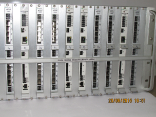
Figure 2: Custom FPGA rack to handle the data from the north half of OWFA. There is a similar rack for the south half of the telescope. These cards re-organize the packetized data from the 264 elements into 8 time-slices, with each time-slice containing the data from all 264 elements. The time slices are transferred to 8 different HPC nodes via ethernet. This allows the HPC nodes to independently carry out the 264 element FX correlation for each time-slice.